
A dipole antenna is a good antenna for
single and multi-band use. The dipole is simple and inexpensive to make. While is possible to install a remote tuner
in the attic and bring coaxial cable down from the antenna system to your
station for a 1:1 SWR on all bands consider the tradeoff between power lost, overall
antenna/tuner costs, and the antenna radiation efficiency.
Keep in mind that physically short
antennas, those whose length is 1/8 wave length or less are extremely
inefficient. For example, a 20 foot long
non-resonant dipole may present a 1:1 SWR with a remote tuner at 80 meters but
the actual signal radiated is only around 10% of the delivered power. In other words, an SWR of 1:1 does not mean
that your antenna radiates well. A 50
ohm resistor placed at the end of a piece of coax will show a 1:1 SWR but will
radiate very little RF.
As an alternative to a remote tuner,
consider using RG8 or LMR400 coax cable rather than RG58 or even RG8X. For feedline lengths of under 100 feet, the
loss due to high SWR is minimal at HF.
For example, the additional loss in a 50 foot length of Belden 9913
(RG8) due to a 3:1 SWR is 0.14 db. The
total feedline loss is 0.37 db. Thus a
100 watt output from a transmitter is reduced to 91.766 watts at the antenna
which is insignificant. Any antenna
tuner, either remote or the one in your radio has a loss of about 10
percent. In other words, even at a
perfect match, you will lose 10 watts in the tuner in your rig or 10 watts in
the remote tuner.
Dipole Lengths (1/2 wave antenna) = 468 Feet / freq(MHZ)
Band MHz Length
10m 28.4 16' 6"
15m 21.1 22' 2"
20m 14.1 33' 2"
40m 7.1 65' 10"
80m 3.6 130' 0"
The
pattern of any HF dipole becomes less and less directive as the antenna height
is reduced below 1/2 wave length above ground.
In addition the elevation pattern approaches that of a sphere – the antenna
approaches an NVIS antenna colloquially known as a “cloud warmer”. See
radiation elevation plot for ¼ vertical vs. dipoles.
Installing Dipole Antennas
If the attic area is not large enough
to accommodate an almost full-size dipole, simply erect as much of the antenna
as possible in a straight line, then bend the ends of the dipole up, down, or
sideways from the main portion of the system
For a balance dipole, attempt to maintain symmetry in the system by
bending the ends of the antenna in equal amounts.
Shortened Dipole Antennas
A physically shortened dipole is a practical alternative to a full size antenna
for the upper HF bands. There are several alternatives for shortening a dipole
antenna to fit in the available space;
- 50%
linear loading line in each leg of the dipole without loss.
- double bazooka with the same results as a linear.
- install a loading inductor in each leg of
the dipole with some loss. Here is a link to information on loaded dipoles
including an interactive calculator:
https://k7mem.com/Ant_Short_Dipole.html
The typical 2 car garage is about 20 foot by 20 foot with
an attic storage space above. A loaded
inverted V dipole for 20 meters can be hung from the top of the roof ridge
truss with the dipole legs extending down to the attic floor along the truss
legs. By adding legs of 22 feet and 16
feet the dipole becomes a fan dipole and covers 20, 15, and 10 meters with a
single feedline. Coverage of 17 and 12
meters can be obtained by using the tuner in your rig or an external tuner.
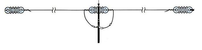
Off Center Fed Dipole Antennas
A variation of the basic dipole is the
OCF or off center feed dipole. A 68 Foot
antenna that can provide a reasonably good match across multiple bands which
are even harmonically related, such as, 80, 40, 20, 10 and 6M. The OCF dipole
is like a standard horizontal dipole but fed at a position other than the
center typically at the 1/3 – 2/3 position. The OCF antenna gives lower SWR
with wider bandwidth over more bands than the small length center fed dipole.
Remember the OCF dipole has an impedance of 200 to 300 Ohms so you will need a
4:1 or 6:1 UNUN if you do not use a remote auto-tuner. See SWR plot for center
vs. OCF feeds. Click here for detail explanation of how the OCF Dipole works.
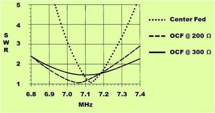
SWR Plot for Center vs. OCF Feeds
BALUNs and UNUNs
A BALUN is a simple device that converts a balanced
source/destination to an unbalanced destination/source. Coax cable is unbalanced. A dipole is for the most part a balance antenna. By placing a 1:1 BALUN as the feed point of
the antenna, we convert the unbalanced feedline into a balance load and keep
the outside of the coax braid from acting as part of the antenna. This reduces RF current flowing on the
outside of the coax shield back into the shack.
A folded dipole has a feed point impedance of 200 ohms which requires a
4:1 BALUN. The BALUN simultaneously
converts from balanced to unbalanced and transforms the
200 ohm feed point impedance to the 50 ohm coax feedline impedance. An UNUN on the other hand is a device that
maintains unbalanced to unbalanced matching but has the primary purpose of
preventing the RF from the antenna flowing down the coax and back into the
shack. It is primarily an RF choke. An UNUN can be placed at the shack end of a
feed line to effectively block any RF current that may be coupled into the
feedline from the antenna from flowing back into the radio. It should also be placed at the feed point of
any unbalanced antenna such as a vertical.
How can you tell if you need an UNUN?
Set your transmitter internal meter to SWR, key your transmitter, and
note the SWR. While keying the
transmitter, place you hand on the feed line or move it around. Does the SWR change? If so then your feedline is behaving as part
of the antenna and could benefit from an UNUN at the transmitter end.
If you would like more information on deed restricted antennas other
interesting presentations click here.
More information on dipole antennas click here